System Syzer Calculator & Instruction Book
System Syzer Calculator & Instruction Book
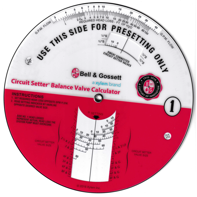
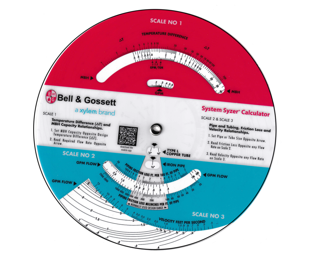
The determination of design data for Hydronic Systems is relatively simple. Often, however, an engineer must consult several different design tables, charts, and formulae to establish GPM flow requirements, pipe size, pipe pressure drops, relative water velocities, pumping heads, system curves, control valve Cv ratings, etc. The B&G System Syzer Calculator consolidates all necessary design information in a simple, easy to use circular slide rule.
The System Syzer Calculator is useful both in final design work and in preliminary system planning. Proposed pump and pipe sizes can be quickly roughed out for estimating purposes. The System Syzer Calculator has five scales sequenced in the same way in which they would typically be used in designing a Hydronic System.
The following states the reference base of the various scales and illustrates their uses with design examples.
Scale #1 – Load / GPM Relationships Scale #1 is stated in terms of temperature difference, MBH and GPM.
Scale #2 – Flow-Pressure Drop Relationships and Pipe Sizing Scale #2 relates GPM flow rate to friction loss for both type “L” copper tubing and for schedule 40 steel pipe. Friction loss is stated in terms of milinches per foot and in feet per 100 feet of pipe. Either milinches per foot of feet per 100 feet are valid expressions of pipe friction loss
Scale #3 – Water Velocity Considerations Scale #3 establishes water velocity in feet per second for any given flow rate through the particular pipe size, or tubing size shown. Water velocity in the hydronic system should be high enough to carry entrained air in the water stream-yet not so high as to cause noise problems.
Scale #4 – Circuit Piping Pressure Drop Scale #4 provides a simple method of determining required pump head from the equivalent circuit piping length and the resistance per unit length.
Instruction book pdf can be viewed Click here.
| TEH-175B | |
| Price | $29.95 |
| Customer Service | We're Here To Help! Call us anytime during our customer service hours... Monday through Friday - 8:30 am to 4:30 pm (Pacific) Order Questions:
TOLL FREE, 800-273-7375 (Outside the U.S. call 818-887-7828). Our Address: 8001 Canoga Avenue Canoga Park, CA 91304 US Phone: 800-275-2665 E-mail: sales@buildersbook.com
|
| Description | System Syzer Calculator & Instruction Book The determination of design data for Hydronic Systems is relatively simple. Often, however, an engineer must consult several different design tables, charts, and formulae to establish GPM flow requirements, pipe size, pipe pressure drops, relative water velocities, pumping heads, system curves, control valve Cv ratings, etc. The B&G System Syzer Calculator consolidates all necessary design information in a simple, easy to use circular slide rule. The System Syzer Calculator is useful both in final design work and in preliminary system planning. Proposed pump and pipe sizes can be quickly roughed out for estimating purposes. The System Syzer Calculator has five scales sequenced in the same way in which they would typically be used in designing a Hydronic System. The following states the reference base of the various scales and illustrates their uses with design examples. Scale #1 – Load / GPM Relationships Scale #1 is stated in terms of temperature difference, MBH and GPM. Scale #2 – Flow-Pressure Drop Relationships and Pipe Sizing Scale #2 relates GPM flow rate to friction loss for both type “L” copper tubing and for schedule 40 steel pipe. Friction loss is stated in terms of milinches per foot and in feet per 100 feet of pipe. Either milinches per foot of feet per 100 feet are valid expressions of pipe friction loss Scale #3 – Water Velocity Considerations Scale #3 establishes water velocity in feet per second for any given flow rate through the particular pipe size, or tubing size shown. Water velocity in the hydronic system should be high enough to carry entrained air in the water stream-yet not so high as to cause noise problems. Scale #4 – Circuit Piping Pressure Drop Scale #4 provides a simple method of determining required pump head from the equivalent circuit piping length and the resistance per unit length. Instruction book pdf can be viewed Click here. |